Universal Wafer Gear Butterfly Valve

A robust, space-saving butterfly valve with a wafer-style body and manual gearbox operation, designed for industrial applications requiring reliable on/off control with enhanced torque capabilities. Compliant with ISO 5752 and API 609 standards. View Technical Specs

View Technical Specs
DIN Resilient Seated NRS Gate Valve

Product Overview

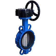
The Universal Wafer Gear Butterfly Valve is engineered as a versatile and robust solution for a wide range of industrial flow control applications. Its compact wafer design allows for easy installation between standard pipe flanges, significantly reducing space requirements and overall system weight compared to other valve types.

Equipped with a heavy-duty manual gearbox actuator, this valve provides precise 90-degree on/off operation with mechanical advantage, making it ideal for larger valve sizes or applications where higher torque is required to overcome seating friction. Its universal design ensures compatibility with a broad spectrum of non-corrosive and mildly corrosive media.

Constructed with a durable ductile iron body and precision-machined disc, the Universal Wafer Gear Butterfly Valve delivers reliable performance and long service life in moderate pressure and temperature conditions, offering exceptional value for standard industrial applications where enhanced operational control is needed.

Key Features & Benefits

Compact Wafer Design

Space-saving body design allows for easy installation between standard pipe flanges, reducing overall system footprint and installation costs.

Manual Gearbox Actuator

Robust gear reduction system provides mechanical advantage for easy operation of larger valves or those with high seating torque requirements.

ISO/API Compliance

Fully compliant with ISO 5752 and API 609 standards for industrial butterfly valve design and performance.

Bi-Directional Sealing

Symmetrical disc design ensures reliable sealing performance in both flow directions, eliminating flow direction restrictions.

Durable Construction

Ductile iron body and stainless steel disc/shaft provide excellent durability and corrosion resistance for long service life.

Lockable Operation

Gearbox design often includes a lockable handle to prevent unauthorized operation and ensure system safety.

Technical Specifications

Basic Parameters

Parameter Specification Range
Nominal Diameter (DN/NPS) DN100 ~ DN1200 (4" ~ 48")
Common Sizes: DN150, DN200, DN300, DN400, DN500, DN600
Nominal Pressure (PN/Class) PN10, PN16, PN25 (10bar to 25bar)
Class 150, Class 300 (285psi to 720psi)
Operating Temperature -20°F ~ 400°F (-29°C ~ 204°C)
Applicable Media Water, Oil, Gas, Steam, Chemicals, Mildly Corrosive Fluids
Sealing Class ISO 5208 Class IV

Material Specifications

Component Material Options Standards/Features
Valve Body Ductile Iron, Carbon Steel EN-GJS-400-15, ASTM A216 WCB, Wafer Style
Disc Stainless Steel AISI 304/316, Precision-Machined for Optimal Sealing
Seat NBR/EPDM/Viton/PTFE Synthetic Rubber or PTFE, Abrasion and Chemical Resistant
Shaft Stainless Steel AISI 304/316, Anti-Corrosive Design
Actuator Manual Gearbox Ductile Iron Housing, Worm Gear Drive, Handwheel Operation

Standards & Compliance

  • Design Standards: ISO 5752, API 609
  • Flange Standards: ISO 7005-1, ANSI B16.5 Class 150/300
  • Testing Standards: ISO 5208, API 598, Hydrostatic and Leakage Testing
  • Certifications: CE, ISO 9001, API 609

Working Principle

The Universal Wafer Gear Butterfly Valve controls fluid flow using a rotating disc and resilient seat mechanism, with operation facilitated by a manual gearbox:

  1. Opening Process: Rotating the handwheel (typically 4-10 turns, depending on gear ratio) turns the worm gear, which in turn rotates the disc 90 degrees to a parallel position with the flow direction, allowing media to pass through with minimal resistance.
  2. Closing Process: Rotating the handwheel in the opposite direction turns the disc to a perpendicular position, compressing the resilient seat (NBR/EPDM/Viton/PTFE) against the disc to create a tight seal and shut off flow. The gearbox provides mechanical advantage for easier operation.
  3. Sealing Assurance: The resilient seat conforms to the disc surface, providing reliable bi-directional sealing even with fluctuating pressures. The gearbox design ensures smooth, controlled operation and precise positioning for on/off control in industrial applications.

Application Areas

General Industry

Chemical processing, power generation, and manufacturing plants requiring robust flow control.

Water & Wastewater

Municipal water supply, wastewater treatment, and large-scale irrigation systems.

Oil & Gas

Upstream, midstream, and downstream applications for oil, gas, and water injection systems.

Power Generation

Boiler feedwater, cooling water, and flue gas desulfurization systems in power plants.

Installation & Maintenance

Installation Guidelines

  • Inspect valve for damage and confirm closed position before installation; clean pipeline flanges to remove debris.
  • Position the valve between two flanges, ensuring the valve body is centered and bolt holes align with flange holes.
  • Install gaskets on both sides of the valve body (if not already integrated) and secure with flange bolts.
  • Tighten flange bolts evenly in a crisscross pattern to avoid uneven pressure on the valve body and ensure proper sealing.
  • Ensure the gearbox is mounted correctly and operating in the proper direction (consult arrow on gearbox for open/close direction).
  • Conduct hydrostatic testing (1.5×PN) and leakage testing after installation before commissioning.

Maintenance Recommendations

  • Regularly inspect the resilient seat for signs of wear, cracking, or deformation; replace the seat if necessary to maintain sealing performance.
  • Lubricate the gearbox annually or as per manufacturer recommendations to ensure smooth operation and prevent corrosion.
  • Check the shaft and disc for corrosion or buildup; clean and lubricate the shaft bearings as needed.
  • Inspect the handwheel and gearbox for loose connections or damage; tighten or replace components as required.
  • For long-term shutdown, flush the valve with clean water to remove any residual media and prevent seat hardening.

Frequently Asked Questions (FAQ)

Q: What is the difference between a lever and gear-operated butterfly valve?

A: Lever-operated valves are manually operated with a direct lever for quick 90° turns, ideal for smaller valves. Gear-operated valves use a worm gearbox to provide mechanical advantage, making them easier to operate for larger valves or those with higher torque requirements.

Q: How many turns does the gearbox require to open/close the valve?

A: The number of turns varies depending on the gear ratio and valve size, typically ranging from 4 to 10 turns for a full 90° rotation. The exact number is specified in the product manual.

Q: Can the gearbox be replaced with an actuator for automated operation?

A: Yes, most gear-operated butterfly valves are designed with a mounting pad that is compatible with electric, pneumatic, or hydraulic actuators for automated control. Contact our technical team for actuator compatibility and specifications.

Q: Is the Universal Wafer Gear Butterfly Valve suitable for high-pressure applications?

A: This valve is designed for moderate to high-pressure applications up to PN25/Class 300. For ultra-high-pressure applications, specialized valves with reinforced bodies and seats may be required. Please consult with our sales team for specific pressure ratings.

Need Custom Solutions?

Our engineering team can customize Universal Wafer Gear Butterfly Valves to meet your specific pressure, temperature, and media requirements. Contact us today for a personalized quote.

Contact Our Technical Team