DIN Angle Globe Valve

A high-performance valve designed to control fluid flow in industrial applications, complying with Deutsches Institut für Normung (DIN) specifications for superior reliability and durability.

View Technical Specs
DIN Resilient Seated NRS Gate Valve

Product Overview

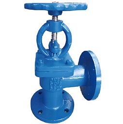
The DIN Angle Globe Valve is a robust and versatile valve designed to control the flow of fluids in pipelines. It features a disc that moves perpendicular to the flow, providing precise regulation and shut-off capabilities. Compliant with Deutsches Institut für Normung (DIN) specifications, this valve is engineered for high-performance applications in industries such as oil and gas, power generation, water treatment, and chemical processing.

Constructed with a durable body (typically carbon steel, stainless steel, or alloy steel) and a precision-machined disc and seat, the DIN Angle Globe Valve offers excellent resistance to corrosion, erosion, and high temperatures. Its compact design allows for easy installation and maintenance, making it a reliable choice for critical flow control systems.

Available in various sizes, pressure ratings, and end connections (flanged, threaded, or welded), the DIN Angle Globe Valve can be customized to meet specific application requirements. It is suitable for both on-off and throttling services, ensuring optimal performance in a wide range of operating conditions.

Key Features & Benefits

DIN Compliance

Manufactured in accordance with Deutsches Institut für Normung (DIN) specifications, ensuring quality, reliability, and compatibility with industry requirements.

Precision Flow Control

The disc's perpendicular movement to the flow allows for accurate throttling and shut-off, ensuring precise control of flow rates.

Durable Construction

Built with high-quality materials such as carbon steel, stainless steel, or alloy steel, providing excellent resistance to corrosion, erosion, and high temperatures.

Easy Maintenance

Designed for straightforward maintenance, with removable internals that allow for inspection, repair, or replacement without removing the valve from the pipeline.

Versatile Applications

Suitable for a wide range of industries, including oil and gas, power generation, water treatment, chemical processing, and more.

Customizable Options

Available in various sizes, pressure ratings, and end connections, allowing for customization to meet specific application requirements.

Technical Specifications

Basic Parameters

Parameter Specification Range
Nominal Diameter (DN) DN15 ~ DN600
Pressure Rating PN10, PN16, PN25, PN40, PN63, PN100, PN160
Operating Temperature -20°C ~ 500°C (Depending on material)
Applicable Media Water, Steam, Oil, Gas, Chemicals, Slurries
Sealing Class EN 12266-1 Class VI

Material Specifications

Component Material Options Standards/Features
Body Carbon Steel, Stainless Steel, Alloy Steel DIN EN 10216-2 P235GH, DIN EN 10216-2 P265GH, DIN EN 10216-5 X5CrNi18-10
Disc Stainless Steel, Alloy Steel DIN EN 10088-2 X5CrNi18-10, DIN EN 10088-2 X2CrNiMo17-12-2
Seat Stellite, Stainless Steel, PTFE High wear resistance, corrosion resistance
End Connection Flanged, Threaded, Welded DIN EN 1092-1, DIN EN 1092-2

Standards & Compliance

  • Design Standards: DIN EN 3311, DIN EN 3312
  • Testing Standards: DIN EN 12266-1, DIN EN 12266-2
  • Certifications: CE, ISO 9001

Working Principle

The DIN Angle Globe Valve operates on a simple mechanism to control fluid flow:

  1. Open Position: When the valve is open, the disc is lifted away from the seat, allowing fluid to flow through the valve body.
  2. Closing Action: To close the valve, the disc is lowered onto the seat, blocking the flow of fluid.
  3. Throttling Control: By partially lifting the disc, the valve can regulate the flow rate, providing precise control over the amount of fluid passing through.
  4. Sealing Mechanism: The disc and seat are precision-machined to create a tight seal, ensuring bubble-tight shut-off when the valve is closed.

Application Areas

Oil & Gas

Used in upstream, midstream, and downstream oil and gas operations for flow control and isolation.

Power Generation

Suitable for power plants, including thermal, nuclear, and renewable energy facilities, for steam and water control.

Water Treatment

Ideal for water and wastewater treatment plants, providing reliable flow control for filtration, disinfection, and distribution systems.

Chemical Processing

Used in chemical plants for handling corrosive and hazardous fluids, ensuring safe and efficient flow control.

Industrial Manufacturing

Suitable for various manufacturing processes, including food and beverage, pharmaceuticals, and pulp and paper.

Marine & Offshore

Designed for marine and offshore applications, including ships, platforms, and subsea systems, for reliable flow control in harsh environments.

Installation & Maintenance

Installation Guidelines

  • Ensure the valve is installed in the correct orientation with the flow direction arrow on the body pointing in the direction of flow.
  • Clean the pipeline and remove any debris before installation to prevent damage to the valve internals.
  • Install the valve between two flanges using appropriate gaskets and bolts. Tighten the bolts evenly in a crisscross pattern to the recommended torque.
  • For horizontal installations, mount the valve with the stem in the vertical position. For vertical installations, ensure the flow is upward.
  • Do not use the valve as a support for the pipeline. Provide adequate support to prevent stress on the valve body.
  • Perform a leak test after installation to ensure proper sealing.

Maintenance Recommendations

  • Inspect the valve regularly for signs of wear, corrosion, or leakage. Replace any damaged components as needed.
  • Lubricate the stem and packing periodically to ensure smooth operation and prevent leakage.
  • Clean the valve internals if there is a buildup of debris or scale that could affect performance.
  • Check the disc and seat alignment to ensure proper closure. Adjust or replace the disc and seat if necessary.
  • Keep records of maintenance activities and replacement parts for future reference.

Frequently Asked Questions (FAQ)

Q: What is the difference between a DIN Angle Globe Valve and a regular Globe Valve?

A: A DIN Angle Globe Valve is specifically designed and manufactured to comply with Deutsches Institut für Normung (DIN) specifications, ensuring quality, reliability, and compatibility with industry requirements. Regular Globe Valves may not meet these specific standards.

Q: Can DIN Angle Globe Valves be used for high-pressure applications?

A: Yes, DIN Angle Globe Valves are available in pressure ratings up to PN160, making them suitable for high-pressure applications in industries such as oil and gas, power generation, and chemical processing.

Q: How do I select the right size DIN Angle Globe Valve for my application?

A: The size of the valve should be based on the nominal pipe size (DN) and the flow rate. It is also important to consider the pressure rating and temperature of the application to ensure the valve can handle the operating conditions.

Q: Are DIN Angle Globe Valves suitable for corrosive applications?

A: Yes, DIN Angle Globe Valves can be made of materials such as stainless steel or alloy steel, which offer excellent resistance to corrosion. The specific material should be selected based on the type of corrosive fluid being handled.

Q: Can DIN Angle Globe Valves be installed in any orientation?

A: DIN Angle Globe Valves are typically installed in horizontal pipelines with the stem in the vertical position. They can also be installed in vertical pipelines with upward flow, but downward flow is not recommended as it may affect the closing performance.

Need Custom Solutions?

Our engineering team can customize DIN Angle Globe Valves to meet your specific pressure, temperature, and media requirements. Contact us today for a personalized quote.

Contact Our Technical Team